The World of Solidworks vs Reality
When I had originally made the CAD drawing I had made the Scan Tower Base structure one solid block with holes made as needed. In reality you have to find a way to machine it and either use glue or screws to keep it together. That means my floating limit switches in Solidworks need actual mounting holes and not just willpower.
This is when I realized I could not 3D print the entire tower because the school did not have large enough 3D printers and it would be too expensive for our budget. The Scan Tower would have to be made using a mixture of laser cutter, 3D printing, and using the mill in the E5 machine shop.
The Cap and Base were the trickiest pieces to determine how to machine. We will see if the people at the machine shop can give me some advice. At first I thought I could use the CNC Mill but it turned out to be hard to use and temperamental. This in turn made me temperamental.
The E5 machine shop did not allow the use of wood in their mills. That's how the material for the Cap and Base that holds the bearings became grey PVC bought at the E3 machine shop. Similarily, it is harder to join an elbow pipe together in reality than in Solidworks so the new design became a mixture of a 3D printed T-shape with set screw and a hole to hold a metal dowel.
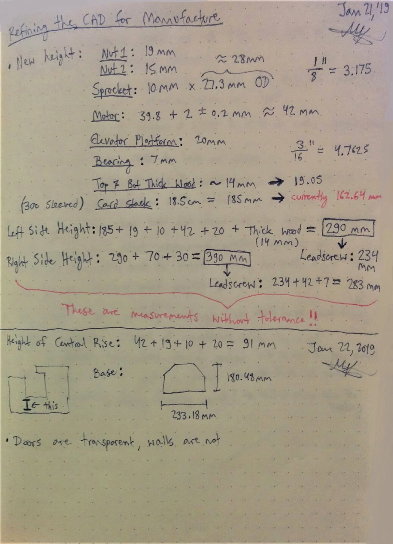
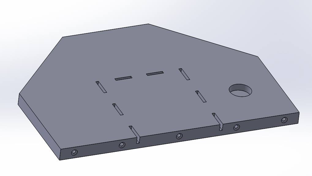
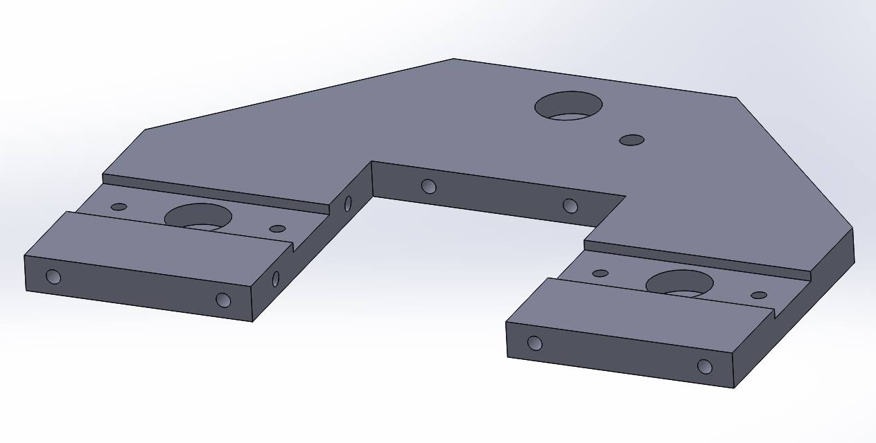
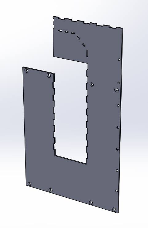
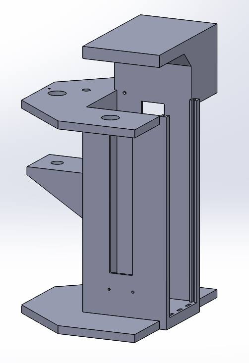
In the gallery below we have some notes on the design of the scan tower, followed by their Solidworks models (bottom, top, side), and the full assembly!