Electrical Update!
The good news: after last semester, most of the electrical components were already selected and we had a schematic diagram.
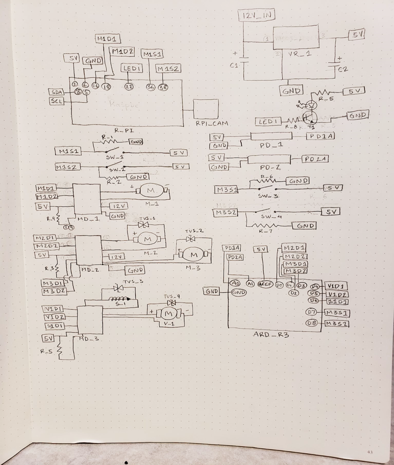
The bad news: the schematic in question was hand-drawn (it’s shown on the left) and some parts had to be re-selected, such as the motor drivers, which were originally specified to handle 1A. Different motor drivers would give a larger safety margin if any of the motors required more current than anticipated.
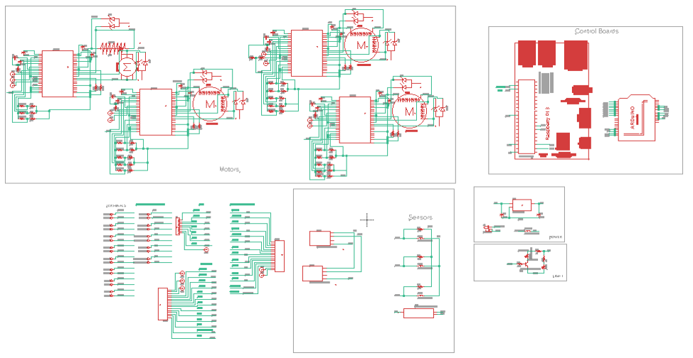
In addition to sensors, drivers, and power modules, we added in an emergency stop and a temperature sensor as safety features. The resulting schematic is down below. There’s a few settings on the motor driver chips that I’m not entirely sure of, so there’s test points and optional jumpers all over the place so we can, hopefully, do this with just one PCB iteration.
Below is the schematic all drawn up properly in EagleCAD!